Datalogging 
See also: Tools and Help in Cscape
Topic Menu
Datalogging Overview

|
Datalogging & Alarm Handling |

|
Energy Monitoring Application: Cscape Example |

|
Combustion Boiler Control Cscape Example |
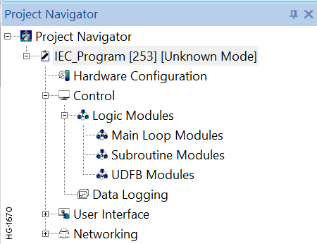
Home > Project Navigator > Control > Data Logging
The Data Log utility is designed to allow any controller with a Removable Media port to periodically log register values to removable media (microSD or CompactFlash). The register data is stored in .CSV (comma separated value) format, which is compatible with 3rd party PC applications, such as Microsoft Excel. With up to 30 register variables in a log group and up to 10 separate log groups, a maximum of 100 register variables can be logged. Each log group has its own configurable timer, which determines how often the log group’s variables will be automatically sampled and logged. In addition, a log group’s variables can be manually sampled and logged, by setting the group’s manual trigger register bit.
NOTE: Firmware version 12.50 or older support up to 10 register variables in a log group instead of 30. However, maximum number of groups and maximum number of variables are 10 and 100 respectively.
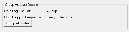
There are Global Attributes, which affect all log groups, such as Global Status and Global Enable Registers, and there are Group Attributes, such as Group Status Register, Manual Trigger Register and Data Log Setup, which are specific to each group.
Return to the Top: Datalogging
Data Logging Configuration
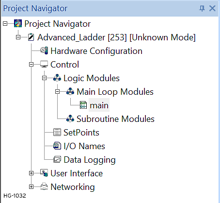
Home > Program > Data Logging or select in the Project Navigator > Program Name > Control > Data Logging
NOTE: Ensure the desired controller is configured in Hardware Configuration .
Open the Data Log Configuration utility by selecting the Datalogging button from the Program Ribbon or open from the Project Navigator, see below.
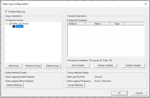
The figure below shows the initial state of the Data Log Configuration dialog. The Enable Data Log checkbox must be checked before Data Log Configuration can proceed.
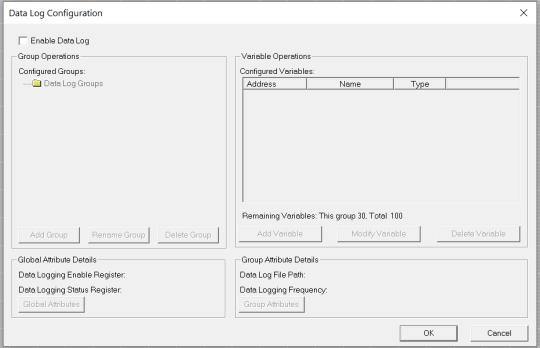
Enable Data Log - Select checkbox to activate or deactivate the Data Log Configuration.
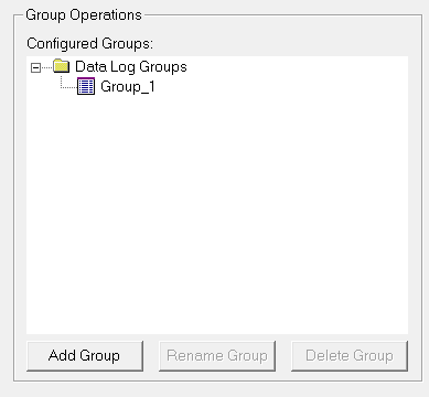
Data Logging Group Operations - In the Group Operations pane, up to 10 log groups can be defined.
Configured Groups: Shows the list of defined log groups.
Add Group: Allows a new log group to be added.
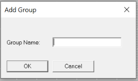
Enter up to 8 characters for the Group Name.
Allowed characters are a-z, A-Z, 0-9 and _.
NOTE: Up to 10 log groups can be configured.
Rename Group: Allows selected log group to be renamed. All other features associated with the log group are unchanged.
Delete Group: Allows selected log group to be deleted.
Return to the Top: Datalogging
Data Logging Variable Configuration
In the Group Operations pane, select the group whose register variables will be configured in the Variable Operations pane.
Step 1:
Step 2: Select a button from Variable Operations pane
Variable Operations in Data Logging
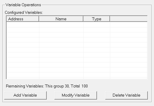
Configured Variables: Shows the list of register variables configured for the selected log group.
Add Variable:
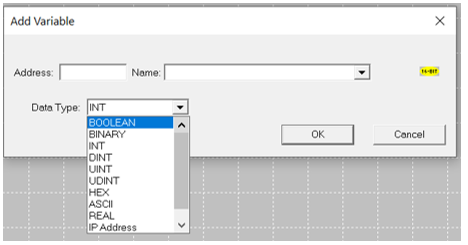
From Cscape 9.50 onwards, Datalog configuration supports adding a variable range
In the Add Variable window, giving the range as, for example, %R1-20 will add %R1 to %R20 variables in the configured variables window. This allows a new register variable to be added to the selected log group and determines how the variable will be formatted in the log file. NOTE: Up to 30 variables can be configured in a group and a total of 100 variables can be configured in datalog configuration.
Modify Variable: Allows selected variable to be edited.
Delete Variable: Allows selected variable to be deleted.
Return to the Top: Datalogging
Global Attributes in Data Logging
Global Attributes affect all log groups. Click on the Global Attributes button to open the Data Log Global Attributes dialog.

Global Status Register in Data Logging
The Global Status Register is optional and specifies a register block where Global Status will be stored. Global Status consists of two 16-bit registers. The 1st register is Media Status, while the 2nd register is Media Percent Full (0 to 100). Possible Media Status Values are as follows:
|
Status (Decimal) |
Description |
|---|---|
|
0 |
Media ready for Data Logging |
|
1 |
Media not formatted |
|
2 |
Media not present |
|
4 |
Media inserted but not yet ready |
|
5 |
Media critical error |
|
6 |
Media protected (%SR174 = 3) |
Global Enable Register in Data Logging
The Global Enable Register is mandatory and specifies a register bit that is set ON or OFF by the application to start or stop Data Logging.
Group Attributes in Data Logging
Group Attributes affect a specific log group. In the Group Operations pane, select the group whose attributes will be configured and then click on the Group Attributes button. See steps below:
Step 1:Select desired group.

Step 2: Select Group Attributes button in the Group Attributes Details pane.
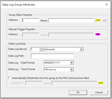
Group Status Register: The Group Status Register is optional and specifies a register block where Group Status will be stored. Group Status consists of two 16-bit registers. The 1st register is Log File Status, while the 2nd register is Group Buffer Percent Full (0 to 100). Possible Log File Status Values are as follows:
| Status (Decimal) | Description |
|---|---|
| 0 | Log file ready to log data |
| 66 | File / Path specified does not exist |
| 73 | Bad file descriptor (corrupt file) |
| 77 | Attempt to open / rename file that is open |
| 81 | Specified file already exist |
| 86 | Function block contains illegal parameter |
| 88 | Too many open files |
| 92 | Attempt to write failed |
| 94 | Sharing violation |
| 95 | No disk present |
| 96 | Directory structure corrupt |
| 98 | Incorrect data format |
Manual Trigger Register: The Manual Trigger Register is optional and specifies a register bit that is set TRUE by the application to cause an additional sample and log of the group’s variables.
Data Log Setup
In the Data Log Setup area, the group’s Data Log Interval, Path and Date / Time Stamp formats are configured.
![]()
Data Log Interval - The Data Log Interval determines how often the log group’s variables are automatically sampled and can be in either seconds (1-60) or in minutes (1-1440). NOTE:"Triggered logging only" should be used for logging alarms and important events. It is not advisable to log data for time interval less than 1 second. If large amount of data is logged it will adversely affect the scan rate of the device which will hamper the performance of the device.
-
If the interval is in seconds, a new log file is created every hour with the file name: MMDDHH.CSV
-
If the interval is in minutes, a new log file is created every day with file name: YYMMDD.CSV
-
If the interval is selected as ‘Triggered Logging Only’, data will be logged only when manual trigger bit is set to TRUE. The data is logged in file name YYMMDD.CSV
Data Log Path - The Data Log Path is optional and indicates where the log group’s folder will be placed on the media. If omitted, the Data Log Path defaults to ”\” in which case the log group’s folder will be placed in the root directory. For example, if the Data Log Path is configured as \MYFOLD\SUBFOLD and the selected group is named GROUP1, the log files for this group will be created in the \MYFOLD\SUBFOLD\GROUP1 folder.
Data Log Date Format - The Data Log Date Format specifies one of twelve date stamp formats to be logged along with each row of the group’s variable data.
Data Log Time Format - The Data Log Time Format specifies one of four time stamp formats to be logged along with each row of the group’s variable data.
Return to the Top: Datalogging
Data Log Operation
When Data Log Configuration is complete and downloaded to the controller, the controller must be in RUN mode and the application must set the Global Enable Register bit to start the Data Log. At this point, each configured group starts sampling and logging data at its specified time interval. Also, each time a group’s Manual Trigger Register goes TRUE, an additional sample and log is performed for the group.
Since media writing is a relatively slow operation, each group first logs its data into an internal RAM buffer, before writing it to the media. The application should monitor the Group Buffer Percent Full status register for each group to make sure that media writing is “keeping up” with each group’s Data Log Interval. If a buffer gets full, data will be lost. In this case, reconfiguring the group’s Data Log Interval for a longer interval is the most likely remedy.
The internal RAM buffer can also help prevent loss of data while the media is removed and replaced. In this case, the application should first write a 1 to %SR174 and then wait for %SR174 to contain a 3, indicating that the media is write-protected and can be safely removed. To prevent data loss, the media should be replaced and %SR174 should be set back to 0 before any of the Group Buffer Percent Full Status registers reach 100%.
Return to the Top: Datalogging